


- Home
- /
- News
- /
- Industry News
Three Phase Electric Power Explained

With that in mind, this article covers a core concept in electrical engineering: three-phase electric power. We’ll start with the basics and work our way up, with the goal that by the end of this article, the magic smoke won’t seem quite so magical.
Electromagnetic Induction
Alternating Current and Electromagnetic Induction
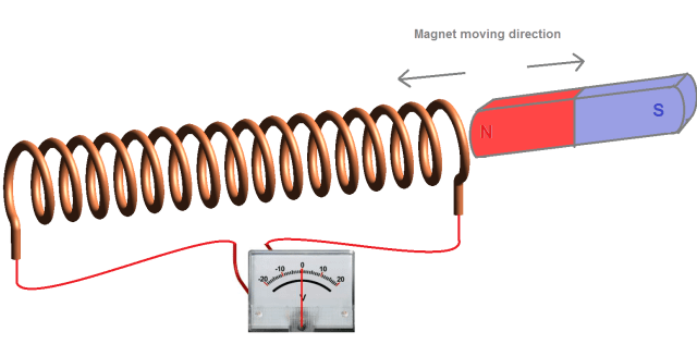
Alternating current (AC) has a sinusoidal shape and changes its direction and amplitude alternately. AC current is generated by an electrical AC generator operating on the electromagnetic induction (EMI) principle. Hence, the electrical generator converts mechanical energy to electrical energy. Its basic parts are a stator and a rotor. The latter represents the magnetic field source while the former contains the conductor where the EMF is induced (generally the conductor is in the form of a coiled wire).
The generator consists of the source of a varying magnetic field (a magnet or electromagnet) and the conductor traversed by magnetic field lines. The electromagnet is a ferromagnet (iron) wound by coil (conductor). The iron becomes the magnet (creates the magnetic field) when an electrical current flows through the coil. Electromagnets are the most commonly used magnetic field source because of their particular advantages in this application (e.g., magnetic strength control, greater magnet power, etc.).
The induced voltage value at the ends of the stator conductors depends on the magnetic field strength (which is proportional to the number of magnetic field lines per unit area), the rate of magnetic field change (the rotating speed of the magnet or conductor) and the angle at which magnetic field lines traverse through the conductor.
In practice, the coil (conductor with more turns) is used instead of a basic conductor in order to achieve a higher EMF value. The EMF value is directly proportional to the number of coil turns N. For example, in the case of a coil with 100 turns, the induced EMF will be 100 times higher than one in a single piece of conductor.
Why Does AC Current Have a Sinusoidal Shape?
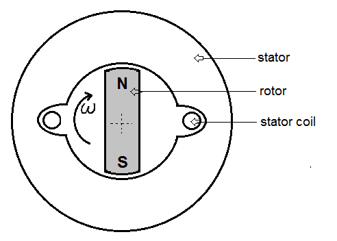
The rotor (magnet) rotates in a magnetic field, making a full 360˚ in a period of time (t). The period t is inversely proportional to the frequency, i.e., t = 1/f. The United States uses a 60-Hz AC system (t = 1/f = 16.67 ms), while Europe uses a 50-Hz system (t = 1/f = 20 ms). This means that a rotor in a 60-Hz generator covers a full 360˚ rotation in 16.67 ms.

The rotor magnet has two poles, north (N) and south (S). When the rotor (magnet) rotates, the opposite magnet poles pass by the coil in each half cycle (180˚), inducing an EMF with reversing polarity. The reversing voltage polarity causes a reversing current direction (i.e., alternating current).
Multiphase AC Generators
A generator can be manufactured with a different number of the coils placed in the stator. One coil in the stator forms a single-phase generator, while several coils make up a multiphase generator. An EMF with equal amplitude is induced in each coil.
The general advantages of a multiphase generator over a single-phase generator with equal power is that the former is smaller, lighter and less expensive. Basically the only physical difference between a single generator and a multiphase generator is the additional coils with accompanying parts in the stator. Each phase generates approximately equal amounts of energy. The generated energy will be multiplied with the number of phases (i.e., installed coils in the generator).
When compared to a single-phase system, a two-phase system requires more wires and thicker conductors but without any additional benefits, which is why it’s not popular in practice.
Three-Phase Generators
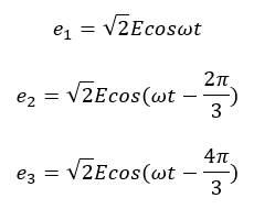
The magnetic field rotates together with the rotor magnet. The EMF induced in each stator coil has the same amplitude and frequency (phase shifted for 120°).
Those three induced EMFs represent the three phases, and the time displacement between them (2π/3) is a phase shift or phase displacement. The reason for shifting the phases is spatial displacement coils in the stator: The coils are physically shifted 120˚ from each other. Basically, the generator construction and its working principle define the shape and the induced voltage value. The common rotor rotates with equal speed, and thus the frequency values of all induced voltages are equal as well.
It is necessary for all three induced EMFs to be even, with equal phase displacement between them. This represents the symmetrical three-phase system.
The sum of the instantaneous voltage values in a symmetrical three-phase system is equal to zero.


- A load of each phase has equal impedance value;
- A load impedance of each phase has equal phase angle;
- Voltage and current values are equal for each phase and;
- Phase displacement is 120˚ between each phase.
In the case of symmetrical three-phase systems, the current does not flow through a common neutral line.
The Three-Phase AC System
Nowadays, the three-phase system serves as the basis of most electrical systems, which consist of energy generation, transmission and consumption. This is one of the most important innovations because it enabled more efficient and simplified energy generation and transmission.
Increasing the power value of the electrical transmission system requires increasing the number of transmission lines (conductors), thus adding to the total cost.
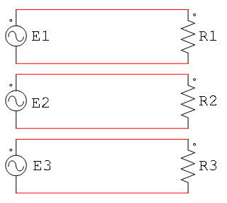
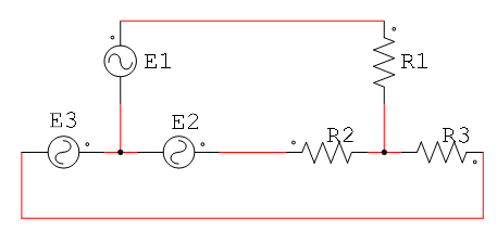
Let’s assume we want 3 times more power transmitted in the system. The diagram below shows three single-phase systems (three generators isolated from each other). This system requires the six lines between the electrical generator and consumer, with each conductor carrying the total current value.
Whereas the diagram above shows a case of three single-phase systems in which six lines are needed to carry the power, the one below illustrates the three-phase system in which only three lines are necessary for the same total power.
Three-Phase System Connections
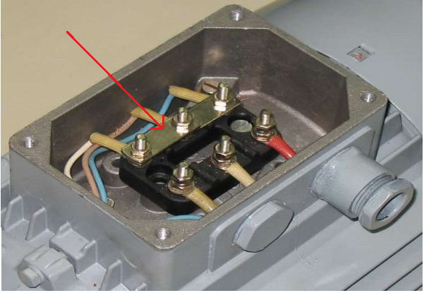
The star connection is formed when the ends of all three stator coils connect in one point (the star point), which is usually grounded. The neutral line can be linked to the star point, but this is not mandatory. The lines connected to the other ends of stator coils are the phase lines (known as phases). The image below shows the stator windings terminals where the star connection is performed.
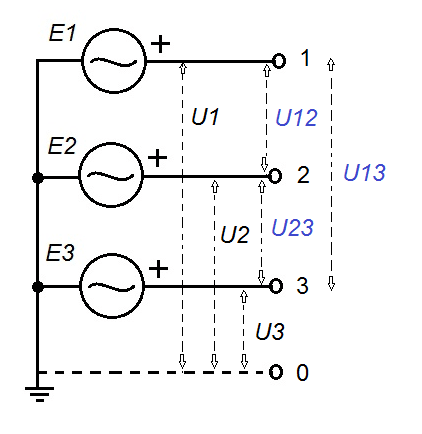
In case of a YN three-phase system, two voltages are available to consumers: line and phase voltage. The consumer is supplied from the line voltage (U12, U23, U13) when it is connected between any two phases, as shown below. Otherwise, if the consumer is supplied from the phase voltage (U1, U2, U3), it is connected between any phase and neutral connection. The line voltage is always times higher than phase voltage value.
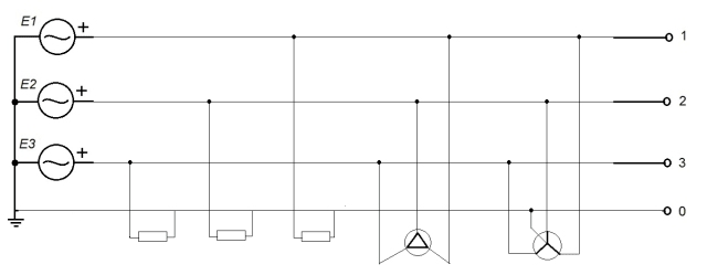
Three-Phase Loads
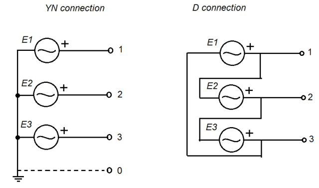
An electrical system is comprised of three main parts: energy generation, energy transmission and energy consumers. The consumers are the loads connected to the electrical system. One of the advantages of a three-phase system is that it can supply both single-phase and three-phase loads. The latter can be connected in a star (YN) or delta (D) connection. The diagram below showcases different variations of load connected to the three-phase system.
Electrical AC Motors
Basically any electrical generator can operate as an electric motor because its construction and working principle are the same. The working principle is based on the mutual induction between stator and rotor windings. The main difference is that the generator converts mechanical energy to electrical energy while the motor converts it inversely.
There are two main types of AC motors: asynchronous and synchronous motors.
Asynchronous Motors
An asynchronous motor—also known as an induction motor—is the most commonly used motor in practice.

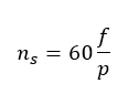
Its working principle is simple and based on Faraday’s law. The AC supply is connected to the stator winding and creates rotating magnetic field (RMF). The alternating flux (magnetic field lines) rotates in synchronous speed, which depends on the supplying voltage frequency:
The EMF is induced in the rotor windings in line with Faraday’s law. The rotor windings are shorted, which enables the current flow. The current through rotor windings produces the force (torque) causing the movement of the rotor (rotation). This rotation and the RMF have the same course.
However, the rotor accelerates to a speed that is always lower than RMF synchronous speed. If the rotor catches up to synchronous speed, the magnetic lines (flux) will not intersect the rotor windings and EMF will not be induced. Thus, the current will not flow through the rotor windings, and the force that rotates the rotor will not be produced.
The rotor will slow down but not stop.
When the rotor speed is lower than the synchronous speed, the magnetic lines intersect the rotor winding, which means the EMF is induced and the rotor spins at the corresponding speed. The rotor speed is approximately close to the synchronous speed but never equal. This is why it’s called an asynchronous motor.
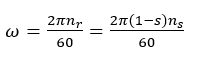
The difference between synchronous speed (ns) and the rotor speed (n) is relative speed or slip:

It is useful to note that a minimum of two phase-shifted currents are necessary for generating the stator RMF. The three-phase current (phase shifted for 120˚ between each other) generates a more uniform RMF than two-phase currents.
This is the most common type of motor, due to its low cost, easy maintenance, robustness, overloading and wide range of rotating speed.
However, its disadvantages are: complex rotating speed regulation, nonlinear dependence of shaft torque on rotation speed and problems during startup.
Synchronous Motors
A synchronous motor’s construction is similar to that of an induction motor. The stator currents produce the RMS, which rotates in synchronous speed (ns). The rotor spins together with RMS in equal speed (n = ns) and the motor is synchronized. The synchronous motor produces a constant speed, which is always equal to the synchronous speed.
In this case, the RMS rotates in high speed and the rotor has large mass and inertia. The magnetic field poles of the stator and rotor are not easily synchronized (“cached”). Consequently, the rotor should be started and sped up to the synchronous speed with the assistance of an external force, after which it can rotate with its own torque. The rotor of a synchronous motor can be started in the following ways:
- Connecting the other auxiliary motor to the rotor shaft
- Asynchronous startup by embedded squirrel-cage conductors (application in large industrial motors)
- Synchronous startup by using variable frequency (increasing the frequency from zero to the final running frequency)
These are more efficient than induction motors in large industrial motor applications. Low-power synchronous motors are used in robotics and servo system applications where high accuracy and precise control are required.
Motor Equivalent Circuits (Steinmetz)
As mentioned above, when the stator windings are connected to the AC supply, the voltage is induced in the rotor windings. Basically, the working principle is the same as a transformer, i.e., the inductive motor is a transformer in which the secondary side rotates. Thus, the equivalent circuit is the same in both cases.
Generally, equivalent circuits give information about main device parameters, such as copper losses and magnetic losses. The motor copper windings are characterized by both resistance (R) and reactance (jX). The common term for both parameters is impedance (Z = R +jX).
Impedance is measured in ohms in its complex form, or it can be indicated as ohms value and impedance phase angle. Because the motor is an inductive load, there is a phase shift between the motor voltage and current. Phase angle represents the phase shift between winding voltage and the current which flows through it.
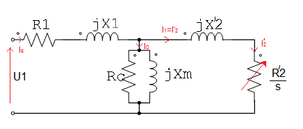
The equivalent circuit is shown in the figure below:
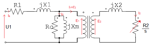
- R1—the resistance of the stator winding
- X1—the stator leakage reactance (caused by flux which does not link with the air gap and rotor)
- Xm—magnetizing reactance required to overcome the air gap
- Rc—iron core losses (hysteresis and eddy current)
- R2—the resistance of the rotor winding
- X2—the reactance of the rotor winding
The air gap between the stator and rotor windings is presented as an ideal transformer. As previously described, in the case of inductive motors, the induced EMF (on the rotor side) is affected by the slip (when the rotor speeds up, slip causes lower EMF induced). This is why the rotor winding resistance is presented as:

Simplified Equivalent Circuits
An equivalent circuit can be simplified by eliminating the ideal transformer and recalculating the rotor’s resistance and reactance to the stator side (primary side). The values are multiplied by k (where k is the turns ratio of the stator and rotor windings).
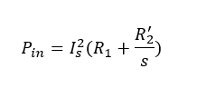
- Stator input power (Pin)
- Stator winding losses
- Iron core losses
- Rotor winding losses
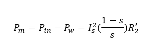
- Power to load (Pm)
- Windage and friction losses
- Output motor power/shaft power (Pout)
These parameters can also be obtained by performing the tests on the motor, specifically DC winding resistance tests (winding resistance and losses information), no-load tests and locked rotor tests (inductance and core losses).
According to the electrical diagram above, equivalent impedance (Zeq) can be presented as:
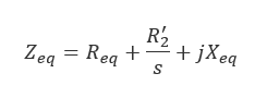

Note that the core losses are neglected: (ls = l's)
The windings copper power loss is given by:

In the real system, with the exception of the copper losses, the output power is also dependent on the rotational losses, including friction loss, windage loss and core loss.
The power (Pin) delivered to the connected load is the difference between the input power and windings losses:


Three-Phase Power
This article was intended to give non-electrical engineers a basic understanding of three-phase power and its application in AC motors. If you have any questions, feel free to post them in the comments below.
Newer articles
- Difference Between Stator & Rotor (19/11/2018)
- Difference between Stepper Motor and DC Motor (19/11/2018)
- Types of DC Motor (26/11/2018)
- IEC Standards for electric motors (07/12/2018)
- Difference Between AC and DC Motor (24/11/2018)
- 5 Strategies to Build a Global Brand (04/12/2018)
- How to Select a Gearmotors (01/10/2019)
- What is a DC Motor? (03/06/2019)
- INSTRUCTIONS FOR GEAR REDUCER MOTOR (01/12/2018)
- What are Brushless DC Motors (31/05/2019)
Older articles
- Difference Between Single Phase and Three Phase Induction Motor (10/11/2018)
- What do IP ratings really mean, and how do they differ from NEMA ratings? (09/11/2018)
- Basic Structure Of Gear Motor Reducer (07/07/2018)
- What are characteristics of planetary gearmotors? (08/08/2018)
- How to Select the Right Gearmotor (05/11/2018)
- We Offer the Largest Inventory of AC and DC Electric Motors (02/11/2018)
- Motor Speeds Explained: When to Use a Gearbox (01/11/2018)
- AC Induction Motor Speeds (02/11/2018)
- How to Choose an Electric Motor (02/11/2018)
- 20 Factors to Consider When You Buy an Electric Motor (02/11/2018)
Join